Last edit: 18/07/2025
Interlocking devices can be classified using a great variety of criteria, e.g. the nature of the link between guard and output system, or the technological type (electromechanical, pneumatic, electronic, etc.) of the output system.
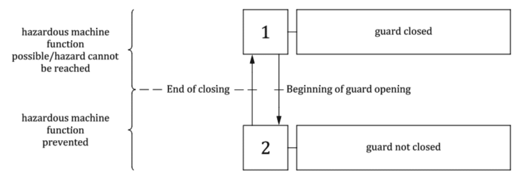
They have a guard position monitoring function that detects whether the guard is closed or not and indicates (a Voltage Free Contact is, for example, opened) when the guard is not in the closed position. An interlocking device can also be used to control other function: e.g. the application of a brake to stop hazardous machine functions before access is possible. Some interlocking device also have a guard-locking function to keep the guard locked while an hazardous movement is present.
Table 1 and the figures below show the classification of interlocking device based upon the actuation principle and the type of actuator.


5.2 Principles of guard interlocking without guard interlocking
In absence of a guard-lock, the Interlock can be opened at any time. That is possible (Risk Assessement) only if the time required to enter the area and be close to the hazard is longer that the time for the harzard to be nullified. For example in case of a dangerous movement, the area can be safeguarded by a normal Interlock only if the time to open the guard and reach the movement is longer than the time for the movement to stop as soon as the gate is opened.
5.3 Principles of guard interlocking with Guard locking
When interlocking with guard locking is used, the opening of the guard is prevented by a guardlocking device, unless all hazardous machine functions associated with this guard have reached a safe. In this configuration, unlocking can take place:
- At any time by an operator, subsequently generating the stop command. The unlocking time must be longer than the stopping time of the hazardous functions (unconditional unlocking);
- Only after the hazardous functions of the machine have been stopped (conditional unlocking).
There are four possible ways to lock a door (Interlock with guard-lock):
- Spring applied – Power-ON released. It is also called “mechanical guard locking”. It means that the guard locking device is moved to the “locked” position by a spring at the removal of power. It is a closed-circuit current principle, in relation to the locking function. When power is provided, the device is unlocked. In case of a black out the door remains locked.
- Power-ON applied – Spring released. It operates in the opposite manner and is called “electrical guard locking”. It is an open-circuit current principle. In order to keep the door locked, power must be present all the time. In case of a blackout, the spring is released, the door unlocks and it can be opened.
- Power-ON applied – Power-ON released. It is a principle that does not change position on the removal of power. It is also called the bistable principle. Power must be applied to change it to the other state. As the removal of the power does not change the position of the guard locking device, this principle is considered a closed-circuit current principle. In case of a blackout, the door lock stays in its last position.
- Power-ON applied – Power-OFF released. It corresponds to an open-circuit current principle, as the guard locking device opens on the removal of the power. It has the same behavior as the second case, but in this one there is no spring. The door is kept closed thanks to an electromagnet. In case of a blackout, the magnet is de-energized, the door unlocks and it can be opened.
There are two reasons to choose an Interlock with guard-locking:
- Either to protect people. For example, inside a safeguarded area there are dangerous movements having inertia. The door is unlocked only when all movements are stopped.
- For manufacturing or Process reasons: you do not want the process to be interrupted at unsuitable times.
Which guard locking principle shall be selected?
If the lock is for production reasons, all four are suitable: the second and the fourth are probably more “flexible.” For machinery protection, the design engineer is completely free to decide which type of guard locking is selected, since it does not represent a safety function.
If a guard locking is for personnel protection, solution 1 and 3 are the ones recommended.
What Are the Safety Signals in an Interlocking Device with Guard Lock?

An interlock has several input and output signals. In the drawing the schematics of Type 2 Interlocking device with guard locking is shown.
The component has the following inputs and outputs:
- One input signal: the one that locks the interlocking device by acting on the Guard Locking Solenoid (number 4 in the picture). In case the locking principle is chosen for people protection, the signal shall come from a safety system. In case of process reason, it can come from a non-safety system.
- Two output signals: Interlocking Monitoring Contacts. They should always be routed to a safety system (number 5 in the picture).
- One or two output signals for the Guard Locking Monitoring Contact. For process reasons, the status can be managed by a General Purpose PLC, otherwise it can be managed by a safety system (number 6 in the picture).
What Safety Functions are Associated to a Guard Interlock
A Guard Interlock can be used on a door that gives access to a safeguarded space. When the interlocking device is activated, all dangerous movements inside the area must be stopped. There are actually two safety functions to be analyzed with a Risk Assessment:
- The Safety related Stop function, when the door is opened.
- The Prevention of unintended start-up while the door remains open.
The two functions may require, in principle, different Performance or SIL levels.
Between the two risks, the latter is probably the most important: the prevention of an unexpected start-up.
If inside the area there is a dangerous movement, normally it is visible. Therefore, in case it is not stopped, when the door is opened, the operator has a good chance to see it and protect himself.
A more dangerous situation is when the movement is stopped, the operator is working on the dangerous part that suddenly restarts: in this case, the person may not have enough time to place himself in a safe position.
Also, the Guard lock has two safety functions to be analyzed in terms of required Performance or SIL level:
- The release of the guard locking device: in other terms, when the door can be unlocked.
- The Safety related Stop function when releasing the guard locking device: in other terms, what has to be stopped, inside the safeguarded space, in case the door unlocks (but it still stays closed).