Last edit: 25/07/2023
Emergency Stop Devices

4.3.1 Emergency stop devices shall be designed to be easily identified and actuated by the operator and others who could need to actuate them.
The actuators of emergency stop devices may be: pushbuttons, wires, ropes or bars, foot-pedals.
Their placement is essential to allow quick access to the emergency stop function. "The actuator of the emergency stop device intended to be actuated by hand should be mounted between 0.6 m and 1.7 m above the level of access (e.g. floor, platform)".
Foot-pedals, should be mounted in a fixed position directly access level (floor level).
The standard requires that emergency stop device shall be located in all places as determined by the risk assessment. In each operator control station, except where the risk assessment indicates that this is not necessary (par.4.3.2). They shall be positioned so that they are directly accessible and do not have sharp elements, edges etc… The size of the machine, the number of hazard zones and operators affects the number and location of emergency devices.
In general, an emergency pushbutton shall be located at each control station. However, risk analysis may justify that there is no emergency button in some positions.
4.3.2 An emergency stop device shall be located:
- At each operator control station, except where the risk assessment indicates that this is not necessary;
- at other locations, as determined by the risk assessment, for example:
- at entrace and exit locations;
- at locations where intervention to the machinery is needed, for example operations with a hold-to-run control function;
- at all places where a man/machine interaction is expected by design
This is also consistent with what is written in the new edition of IEC EN 60204-1, paragraph 10.7.1.
Detectability and Background of the Emergency Stop Device
The detectability of the actuator is fundamental.
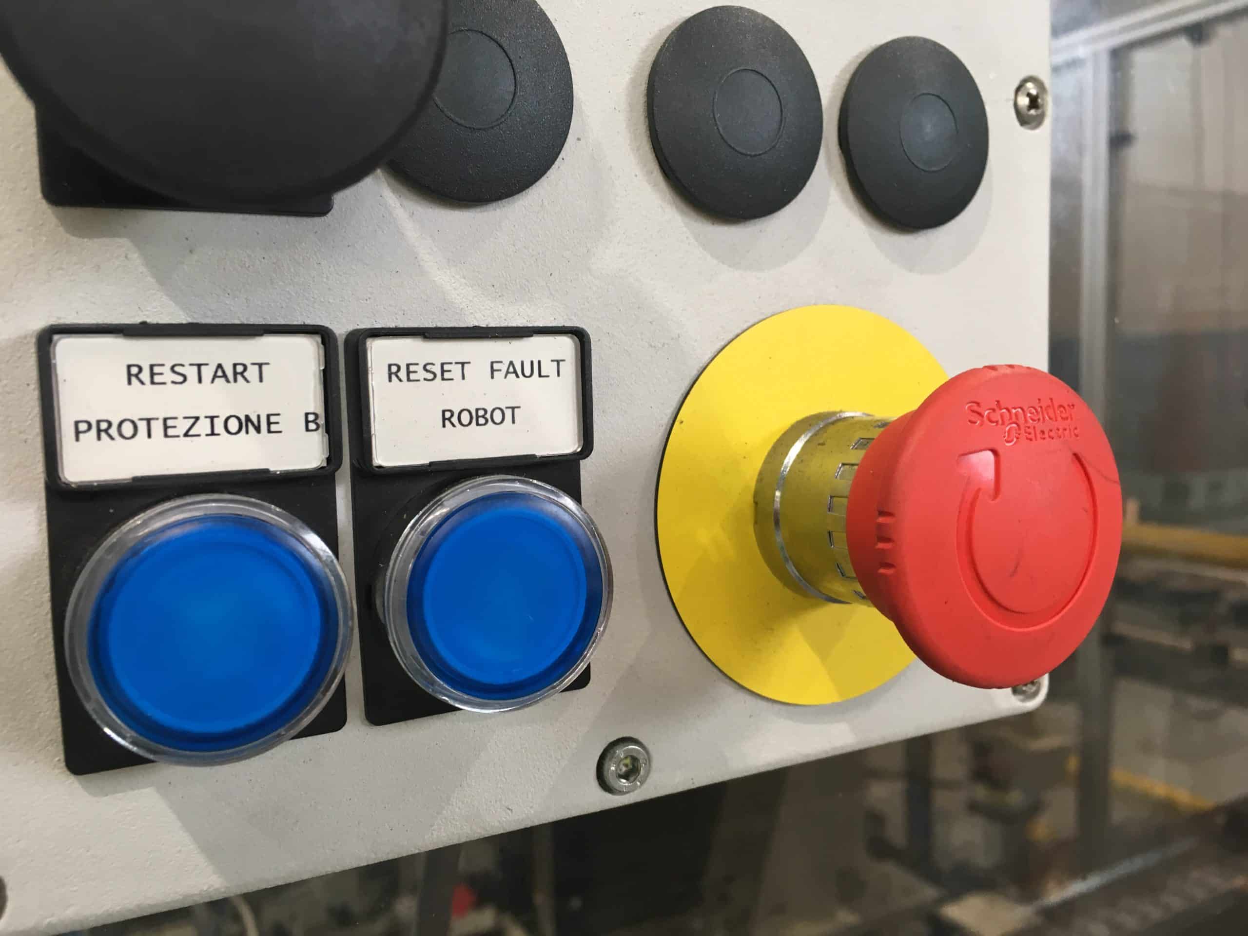
4.3.6 The actuator of the emergency stop device shall be coloured RED[…]
To increase visibility, the color red should be in contrast with the background on which it is placed:
4.3.6 As far as the background exists behind the actuator and as far as it is practicable, the background shall be coloured YELLOW.
The English version of the EN ISO 13850 This is light contrast to EN 60204-1, which says: "If there is a background immediately behind the actuator of the device, it shall be colored YELLOW."
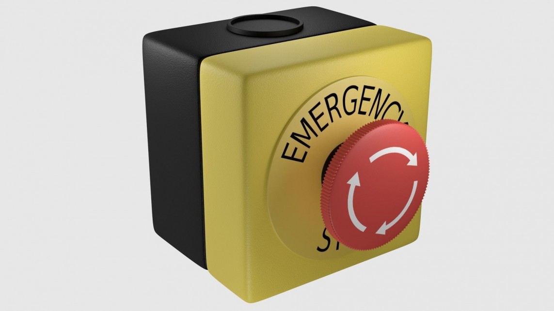
The New Standard (November 2015) requires that neither the actuator nor the background should be labelled with text or symbols. The only symbol you can use is the one shown in the figure and present in the IEC 60417-5638:
4.3.7 Neither the actuator nor the background should be labelled with texts or symbols. Where a symbol is needed for clarification, the symbol from IEC 60417-5638 must be used.
Using keys to disengage Emergency Stop Devices

4.3.6 […] Emergency stop devices requiring a key on the actuator to be disengaged should be avoided.
When an emergency stop actuator can only be disengaged by using a key, to avoid injuries to hand, instruction for use of the machine shall describe the correct use of the key and provide a warning that the key should only be in the actuator of the device to disengage the actuator.
Finally, the standard discourages the use of emergency stop devices with a key (photo on the side): one of the reasons is that if the key remains permanently inserted, the activation of the emergency can result in injuries to the hand. Then, the keys shall be removed from the device.