Last edit: 29/02/2024
Short circuit between any two conductors
Figure 4.16 {4.11.3.1.1} shows an output subsystem in Architecture D or Category 4. Provided both contactors and the Safety Module are inside the same control panel, it is possible to use the scheme shown in Figure 4.17 {4.11.3.1.2} and do a fault exclusion for the probability of a short circuit of the cable connecting the output of the Safety Module with the contactors KP1 and KP2.
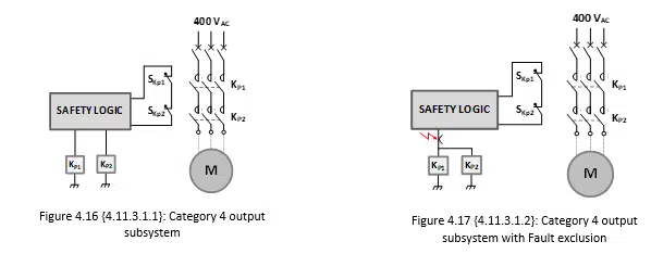
That possibility is stated in ISO 13849-2, Table D-4.

Welding of contact elements in contactors
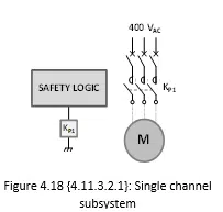
Manufacturers may consider to adopt the architecture shown in Figure 4.18 {4.11.3.2.1} and claim that a PL = d or a SIL 2 level of reliability can be reached. In order to make that possible, a fault exclusion on the contactor KP1 is needed. However that is not allowed by neither IEC 62061 nor ISO 13849-1. That is clearly stated in ISO 13849-2, Table D.9.
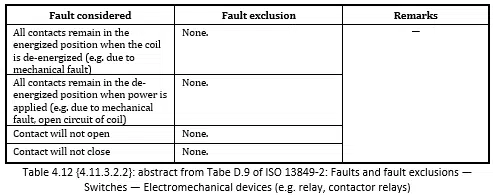
In other words, it is not possible to claim compliance with neither of the two standards for high demand mode Safety systems when a fault exclusion is applied on the Non-opening of contact elements due to permanent welding. That is valid even in case the value of the nominal current of the contactor overcurrent protective device has a safety factor of 0,6 or lower.
The reason is that a contactor has to be protected from overloads and short circuits with a proper overcurrent protective device (Branch Circuit Protective Device, in North American language): the reason is to avoid systematic failures. Once that is done, the contactor random failure rates can be considered “real”. The fact of “over protecting” the contactor may increase its B10D value but it is not correct to claim an infinite value of B10D. ISO 13849-1, table C.1, states a value of B10D of 400.000 in case the contactor is subject to a current equal to its “nominal load”. It also indicates a B10D of 20.000.000 in case the contactor is subject to a “small load” (meaning 20% of its nominal load). Please also refer to §4.12.3.2.
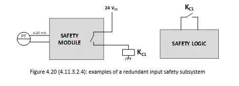
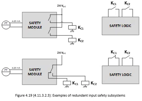
Those considerations are also valid for auxiliary contactors used as inputs of a safety logic. Figure 4.19 {4.11.3.2.3} shows two examples of input subsystems (Pressure Transmitter, a safety module with an internal threshold and auxiliary contactors) that can reach PL d or SIL 2.
However, using the architecture shown in Figure 4.20 {4.11.3.2.4}, a maximum of PL c or SIL 1 can be reached.
