Last edit: 20/06/2023
Historically, this was the only way to determine the maximum SIL that can be claimed by a Safety Function. Here are the steps to be followed: IEC 61508-2, § 7.4.4.2
- Divide the Safety-related system in subsystems.
- For each subsystem calculate the Safe Failure Fraction for all elements in the subsystem separately. In case of redundant element configurations, the SFF may be calculated by taking into consideration the additional diagnostics that may be available (e.g. by comparison of redundant elements).
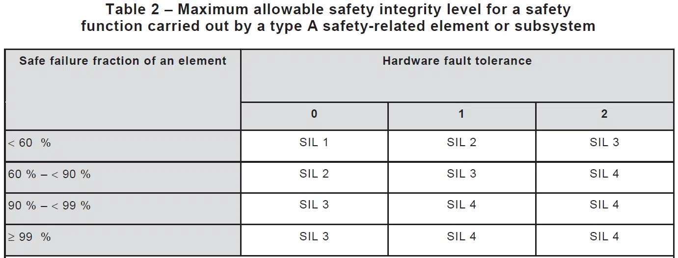
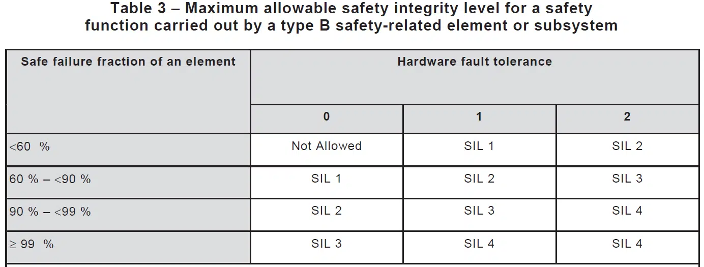
- For each element, use the achieved Safe Failure Fraction and Hardware Fault Tolerance of 0 to determine the maximum safety integrity level that can be claimed from column 2 of Table 2 of IEC 61502-2 for Type A elements; in case of Type B elements, Table 3 of IEC 61502-2 must be used.
- The maximum safety integrity level that can be claimed for an E/E/PE safety-related system shall be determined by the subsystem that has achieved the lowest safety integrity level.
For a Route 1H, each safety component must have all the failure rates coming from a FMEDA Analysis.


The concept Hardware Fault Tolerance (HFT) is used in IEC 61508 series to indicate the ability of a hardware subsystem to continue performing a required function, in the presence of faults or errors. The HFT is given as a digit, where HFT = 0 means that, in case of one fault, the function (e.g., a pressure measurement) is lost. HFT = 1 means that if a channel fails, there is other one that is able to perform the same function: in other terms, the subsystem can tolerate one failure and still be able to function. A subsystem of three channels that are voted 2oo3 is functioning as long as two of its three channels are functioning. This means the subsystem can tolerate one channel failure and still function normally. The Hardware Fault Tolerance of the 2oo3 voted group is, therefore, HFT = 1. In figure 1 an input subsystem with HFT = 1 is shown: I1 and I2 could be two identical pressure transmitters.
How to use a safety component
Going back to our Safety Pressure Transmitter with SFF = 92,8% and Systematic Capability SC 2 we conclude that:
- Having and SFF in the range 90% to 99% and being a Type B, table 3 of IEC 61508-2 indicates that, if it is used as a single component in a Safety Instrumented System, its subsystem can reach, at best, SIL 2; even if its PFDavg indicate, for example, a SIL 3 reliability level.
- Having a Systematic capability SC 2, even if used in a 1oo2 configuration (HFT = 1), the maximum SIL level the subsystem can reach is still SIL 2 (and not SIL 3 as indicated in table 3), due to the limit imposed by its Systematic Capability.