Last edit: 21/06/2025

Among the commands of a machine, probably, the emergency stop is the most visible one; however it is not the easiest to understand.
The reference standard is ISO 13850, which latest edition was published in November 2015: “Safety of machinery – Emergency Stop Function – Principles for design”.
The definition is (§3.1): ”function which is intended to avert arising or reduce existing hazard to person, damage to machinery or to work in progress; and be initiated by a single human action”.
In this article some important aspects are discussed; Please refer to the standard to understand all the requirements and for a correct implementation of the function.
1. The emergency stop function does not perform risk reduction.
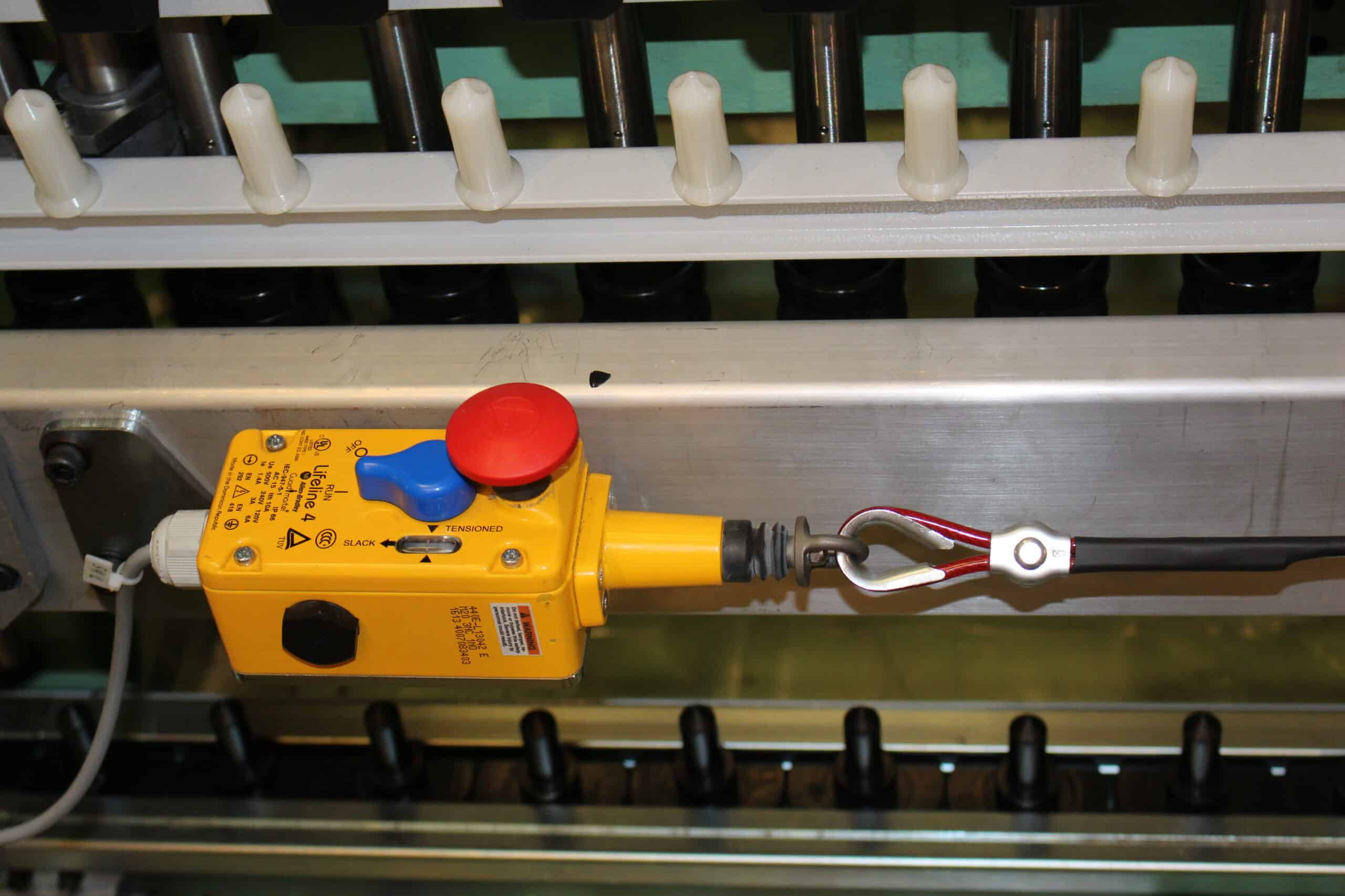
In other words, let’s suppose we are doing a risk assessement of a conveyor belt which moving parts are not properly protected. It is not possible to decide that, thanks to the presence of an emergency rope, the risk is acceptable.
The Machinery Directive is clear [RESS 1.2.4.3]: “Emergency stop devices must be a back-up to other safeguarding measures and not a substitute for them”.
ISO 13850 states that principle in §4.1.1.3 “The emergency stop function is a complementary protective measure and shall not be applied as a substitute for safeguarding measures and other functions or safety functions”.
Another way to present the same concept is to say that the emergency stop is not a safety function, even if it is implemented in a safety system. The definition of a safety function is (§3.5): “Function of a machine whose failure can result an immediate increase of risk(s)”.
That can be defined as the ISO TC 199 Position.
A sligtly different version is that the Emergency stop is a Safety Function since it must have a minimum reliability level (SIL 1 or PL c), however it cannot be used as a Protective Device.
An even more extreme position is supported by a minority of technicians in ISO TC 199 but by a majority in the USA. That is the reason B11.19 recognizes the possibility, in extreme cases where there is no other solution, to reduce the risk thanks to a an emergency stop function like a rope or a button. Here is the language used:
[B11.19: 2019] 10.12 Emergency stop (E-stop) devices
10.12.1 General requirements for E-stop devices
10.12.1.1 Emergency stop devices used to reduce risk to individuals shall comply with all applicable requirements of clause 9 and subclause 10.1.
The topic is regularly discussed at technical tables. GT Enginering believes that the emergency stop function should never be used to reduce risk, since a correct risk reduction measure can always be found.
2. The emergency stop function should not necessary remove all energies.
“The purpose of the emergency stop function is to avert actual or impeding emergency situations arising from the behavior of persons or from an unexpected hazardous event” §4.1.1.1.
Let’s consider, for example, a robot that moves a glass sheet using suction cups. The safe movement of the load is guaranteed by the presence of aspiration in the suction cups. Assume that the activation of the emergency stop function also switches off the vacuum pump. If the activation of the function occurs during a movement of the load, this would involve the detachment of the glass sheets and its projection against the perimeter guarding. In this case it is better not to link the vacuum pump to the emergency stop and manage the risk of the presence of pneumatic energy using Information for Use (Instruction Manual and Signs and Labels).
3. The emergency stop function should not necessary switch off all machines on a production line.
On a production line, or in a system composed by several machines, it is natural to stop all machineries of the line or plant when any Emergency stop is activated. Is clear that this should be the first condition to consider. Imagine a line of conveyors crossing different areas of a large plant; the stop of one conveyor of the line would cause the arrest of all upstream, but not necessarily of those downstream.
The EN ISO 13850 standard details this situation in §4.1.2.
[ISO 13850:2015] 4.1.2 Span of control of emergency stop device(s)
The span of control of each emergency stop device shall cover the whole machine. As an exception, a single span of control may not be appropriate when, for example, stopping all linked machinery could create additional hazards or unnecessarily affect production. Each span of control can cover section(s) of a machine, an entire machine or a group of machines “.
The machinery Directive has a E.H.S.R. that clarify that aspect:
[2006/42/EC] 1.2.4.4. Assembly of machinery
In the case of machinery or parts of machinery designed to work together, the machinery must be designed and constructed in such a way that the stop controls, including the emergency stop devices, can stop not only the machinery itself but also all related equipment, if its continued operation may be dangerous.
Of course, there is the need to indicate, in an intuitive way for the user, which part of the plant is stopped by the specific emergency actuator: this is called “Span of Control”.

4. It is not allowed to use the emergency stop function to perform maintenance on the machine.
Often, the emergency button has a key. This is because, when the key is removed, if the actuator is activated it cannot be reset without the key being reinserted. This gives importance to the activation of the emergency function and to its reset.
However, the key is sometimes used by maintenance to ensure that nobody resets the function and starts the machine: a kind of Lockout-Tagout, or, as the standard states, “prevention of unexpected startup”. This behaviour is not correct. That is written in the standard EN ISO 13850, note §4.1.1.2. “The emergency stop function cannot be considered as measure of prevention of unexpected start up as described in ISO 12100″. The EN ISO 14118, published in May 2018, contains a similar question in the note of §6.3.2.
It can be misleading that some emergency buttons are provided with a key. One cound understand that the purpose of the key is, once the emergency button has been activated, to remove it so that no one can restart the machine.
In reality, this is not the case: the standard discourages the use of Emergnecy push buttons with a key. Here is the language we refer to.
[ISO 13850: 2015] 4.3.6. […] Emergency stop device requiring a key on the actuator to be disengaged (unlatched) should be avoided. When an emergency stop actuator can only be disengaged by using a key, to avoid injuries to hands, instruction for use of the machine shall describe the correct use of the key and provide a warning that the key should only be in the actuator of the device to disengage the actuator.
Therefore, we recommend you do not use Emergnecy push buttons with keys!

5. The background of the emergency button must be yellow.
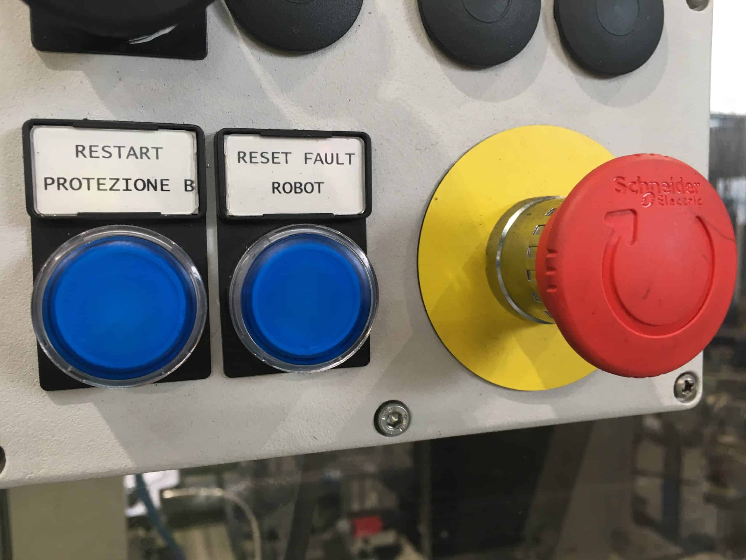
The Emergency stop buttom must be Red with a Yellow background, if a background exists.
[ISO 13850: 2015] §4.3.6: “The actuator of the emergency stop device shall be coloured RED. As far as a background exists behind the actuator and as far it is praticable, the background must be YELLOW”.
The apparent “exception” given by the phrase “As far as a background exists behind the actuator and as far it is praticable” does not refer to the classic “mushroom”, which must be red on a yellow background. It refers, for example, to an emergency rope, whereby, normally it has no background, or the background is part of the frame of the machine. In that case, the standard does not rquire to paint that part of the frame yellow
6. Though the emergency stop function does not reduce risk, it must have a minimum level of reliability: SIL 1 or PLr = c.
The new edition of the standard specifies this in
§4.1.5.1 “Determination of the Performance Level (PL) or SIL required should take into account the purpose of the emergency stop function, but the minimum level required is PLr c or SIL 1″.
7. Usually, the emergency button must not have obstacles that limit the possibility of its activation.
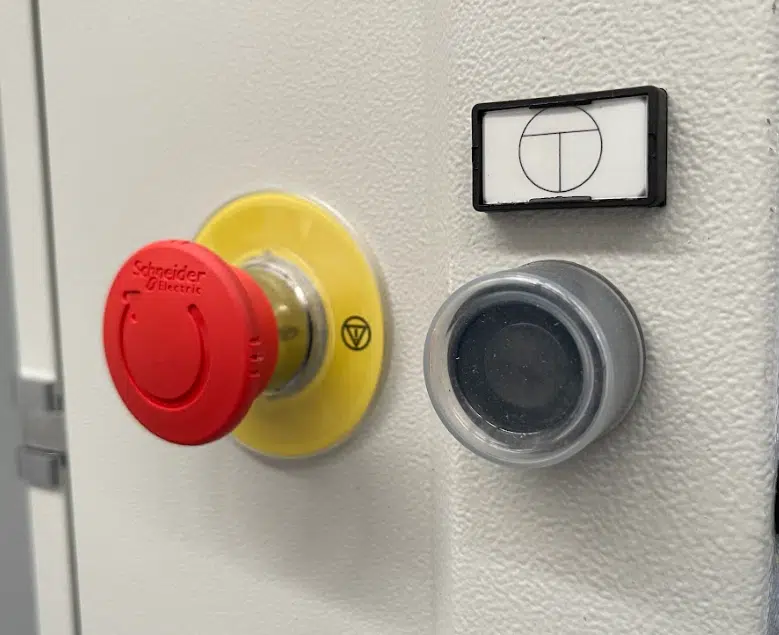
However, the standard recognises that the emergency push button can be activated accidentally and create a problem for the production process. In order to avoid the accedentally activation of the function, incorrect behaviours, like those in the pictures, are detected. It is allowed, as an exception, to protect the mushroom with a shroud or other methods of protection. Hereafter the language in the standard,
§4.5: "The use of a protective shroud around the emergency stop device should be avoided, except when necessary to prevent unintended actuation and other measures are not practicable".
The standard continues by prescribing that such shroud "Shall not impede or hinder actuation with the palm of the hand". Bottom line is that a protection is allowed provided it is possible to activate the function with the palm of the hand.

8. There is no obligation to put an emergency button on each control station.
The standard has always established the fact that, though it is correct, it is not necessary an emergency button on each control station. This decision must be taken following a risk analysis, as prescribed in §4.3.2. The obligation derives from the current edition of EN 60204-1. However, the new edition of this standard (2016), is aligned with EN ISO 13850; please refer to the new language in §10.7.1.
9. The emergency stop function can activate movements, if these are necessary to stop dangerous movements.
For example, please consider the safe arrest of a continuous steel casting line. It occurs only by closing the steel flow from the tundish mould line and thus preventing the steel from continuing flowing into the mould and the cooling chamber. This is done by closing the “tundish hole” using for example a small cup.
It is clear that the risk analysis must lead to precautions to ensure that the closure of the line, caused by the activation of the emergency stop function, does not involve risks for the operator. Please read the language in §4.1.1.5 of the standard.

10. Stop devices covering the start and the stop-contact can not provide the emergency stop function.
Stop devices covering the start and the stop-contact such as the flap stop (Fig. 4), is a special kind of ”stop device” produced normally outside the EU, and used as a normal emergency stop for different machinery, in particular for smaller machines, such as bench drilling machines.
The flap-stop is a start and stop contact, which is equipped with a yellow flap and a red mushroom-type push button (Fig. 4), covering both the start and the stop contacts.
When the mushroom push button is activated, the flap will press the stop button into a stop command position. The flap can be kept in an open position which cannot assure the availability at all times.
The flap stop can therefore not provide the emergency stop function as required in Annex I section 1.2.4.3 of the Machinery Directive 2006/42/EC.
11. The emergency stop function does not need any RESET function.
The RESET function is needed for example when we want to reduce the risk of Whole Body Access. In that case it is a Safety Function.
The emergency stop button or rope is not associated to any Safeguarded Space and therefore it does not need to be reset. However the emergency stop function needs to be Disengaged. Here the normative language:
[ISO 13850: 2015] 4.1.4 Disengagement (e.g. unlatching) of the emergency stop device.
The effect of an activated emergency stop device shall be sustained until the actuator of the emergency stop device has been disengaged. This disengagement shall only be possible by an intentional human action on the device where the command has been initiated. The disengagement of the device shall not restart the machinery but only permit restarting.
That means, for example, that a safety bumper cannot be used as an emergency stop, since it does not have the possibility of being mechanically disengaged.

12. A Switch Disconnector can be used as the Emergency Stop function
The text of the Guide to the MACHINE DIRECTIVE is given:
[Guide to the Machinery Directive : 2019] Disconnecting device as emergency stop
According to market observations, also the disconnecting device as shown in figure at the side is used as emergency stop device. The supply disconnecting device is sometimes being locally operated to serve the function of emergency stop with regard to EN 60204-1 Safety of machinery – Electrical equipment of machines – Part 1: General requirements in which it is stated under section 10.7.4 “Local operation of the supply disconnecting device to effect emergency stop”:
The Guide therefore states that it is possible to use a disconnecting device as an emergency stop. The power isolating device can be operated locally to perform the emergency stop function in accordance with EN 60204-1 Safety of machinery – Electrical equipment of machines – Part 1: General requirements’ where it is stated in section 10.7.4 ‘Operation of the power isolating device to perform an emergency stop’.
However, when the switch disconnector is used as an emergency stop, it makes no sense to speak of a reliability level according to ISO 13849-1 or IEC 62061. The reason is that this component is not part of the machinery control system, since it only acts on the power side.